IVR Call
Flow Diagram
A Call Flow Diagram in IVR Studio is a graph that specifies an
IVR application. A call flow diagram is similar to a voicemail
system user manual. It consists of elements and transitions among
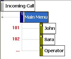
elements. The following figure is part of a call flow diagram:

An element (node) in the above graph
represents a specific stage of an IVR application. For example,
the element labeled Main Menu represents a stage that an
incoming call is just answered by the IVR system. An element also
contains prompts and actions. For example, The Main Menu
element prompts the caller to enter the mailbox number and then
wait for caller input.
A call flow diagram is organized as a tree structure. An element
that contains other elements is called a parent element; and the
contained element is called child element. An element has properties, which
include general information (element name, transition keys, etc),
prompts and actions. Prompts are
audio played over the phone by the system. For example, the
prompts for Main Menu can be voice prompts for the caller
to press 101 to talk to John, press 102 to talk to Sarah. A
transition is a change or a link from
one element to another. With the exception of a jump element, a
transition is defined from a parent element to a child element. A transition is usually caused by some caller
responses, such as pressing some touch tone keys. For example,
after a caller presses key 1, 0, and 1, the active element is
changed from Main Menu to John. A call flow
diagram in IVR Studio defines an IVR application completely. For
example, the above figure defines a simple auto-attendant
application. Once it is deployed, the Voicent Gateway will behave
as your auto-attendant system for incoming calls. |